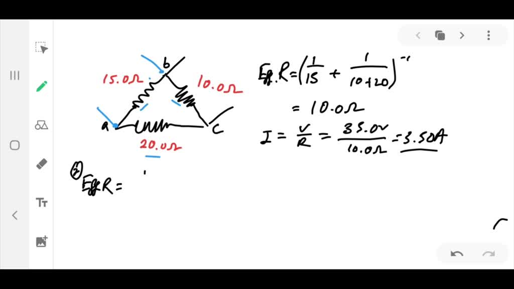
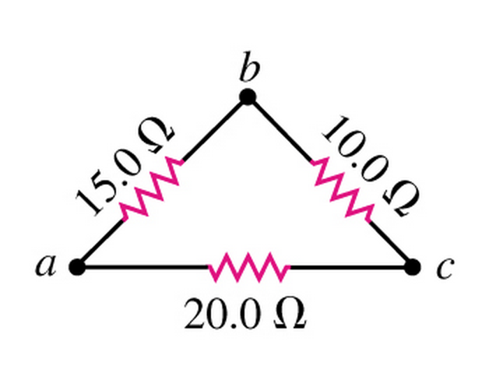
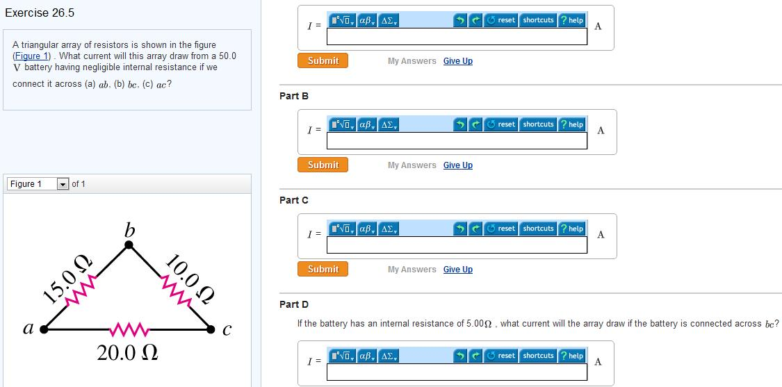
A Triangular Array of Resistors Is Shown in
Figure 71 illustrates operation of a basic half-wave resonant dipole antenna. Customer 0 Topic.

Solved Part A Triangular Array Of Resistors Is Shown In The Chegg Com
Ro as shown in Figure below.

. The junction where the resistors meet is called the summing junction or the virtual ground. Is 3 Q Q f. 1a Kirchhoffs loop equation can be written as 2 Δ V.
Determine the transfer function of the phase lag network shown in the figure Solution. Also from small signal model of shown in above Figure. The balanced nature of the ideal circuit ensures that identical current will exist on each side of the dipole.
Well be using MATLAB script for generating the sample. PAOLA Juan y tú son amigos 3. The binary input goes into the resistors and the analog output is obtained on the output of the op-amp.
Represents the final charge on the capacitor that accumulates after an infinite length of time R is the circuit resistance and C is the capacitance of. 1 e t RC where. A resistor divider is used to generate a 125 mV bias across the AD7124-8s input overcoming the 15 µV maximum offset voltage and ensuring that ADC readings are always positive.
2 Δ V. The length of the lookup table is denoted as Ns or the number of sample points per complete cycle. The lookup table is an array of unsigned integer values that represents the sample points of a specific waveform for a complete cycle from 0 to 2π.
Figure shows the network in s-domain By KVL in the left hand- mesh By KVL in the right-hand- mesh. The circuit is reduced to an array of conductances which are placed in the matrix to form the equations G V I. The solution to is Eq.
Array December 21st 2021. D t 0. Array to string conversion in home.
When a circuit includes nonlinear elements SPICE uses multiple iterations of the linear equations to account for the non-linearities. WaveForms Reference Manual WaveForms is the virtual instrument suite for Electronics Explorer Digital Discovery Analog Discovery Analog Discovery 2 and Analog Discovery Studio devices. Shown in Figure 71a is a dipole antenna excited from an RF source.
By applying KCL at point A If we consider the non Ideal effect such as channel length modulation in the CS amplifier then the small signal model includes one more resistor ie. The more sample points per cycle the better the output waveform. Enter the email address you signed up with and well email you a reset link.
The test circuit shown in Figure 6 ensures that the input is always positive. FERNANDO 2 Por qué Porque deseo hablar con él. For the Arduino changing γ results in either.
The values of these resistors are chosen carefully to produce a binary-weighted summation for the digital inputs. By applying KVL In order to calculate the output impedance R out consider the circuit shown in Figure below. I really appreciate it at such a difficult time for me.
The most up to date version of the following material is located in the Help tab in the WaveForms application. Current near the ends of the dipole is of necessity small vanishing at the ends because electrons whose movement. Es mi compañero de cuarto.
The AD7124 input mode is set to unipolar so only positive values are valid. Where again x is the variable ranging from 0 - NFor the Gaussian the constant α represents the maximum amplitude of the PWM output 255 for the Uno boardAdditionally the constant β here is 05 as it needs to be symmetric around xFinally the constant γ represents a parameter that controls the width of the wave. For the circuit shown in Fig.
Therapeutic Techniques With Children and Adolescents Subject. D t 0. The Help tab is located to the right of the Welcome Instrument menu tab.
Thanks for getting the assignment done in a timely fashion. Click for full size image. SPICE makes an initial guess at the node voltages then calculates the branch currents based on the conductances in the.
The transfer function from the above two equations is given by.

Solved A Triangular Array Of Resistors Is Shown In Fig E26 5 What Current Will This Array Draw From A 35 0 V Battery Having Negligible Internal Resistance If We Connect It Across A

Solved A Triangular Array Of Resistors Is Shown In The Chegg Com

Solved A Triangular Array Of Resistors Is Shown In The Chegg Com

Solved A Triangular Array Of Resistors Is Shown In The Chegg Com
No comments for "A Triangular Array of Resistors Is Shown in"
Post a Comment